High voltage Pockels Cells driver amplifiers
Q-switch step high voltage pulse generators
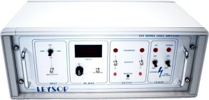
250 Series High Voltage Video Amplifier
High voltage video amplifier for driving electro-optic modulators
 This is a linear Class A output video amplifier with a maximum differential output of 275V over the range d.c. to 7MHz. The two outputs can also be set to ±250V dc relative to each other using a bias control. This facility allows an electro-optic amplitude modulator to be set to any desired light output intensity level for any input signal level. This output bias does not introduce any limit to the signal output range.
The amplifier has been designed to drive electro-optic modulators from the EM200 range where the load is purely capacitive and does not exceed 100pf. The output is short circuit proof.
Specifications
| Signal output voltage range | 275Vdc - 6MHz bandwidth |
| Amplifier Square Wave Rise & Fall Time using 100pf load | < 65 ns (10% - 90%) |
| Bias Voltage Range | +250V to -250V |
| Input Voltage for Full Output | ±1Vdc or 2Vpp., ac |
| Input Impedance | 50Ω nominal |
| Cabinet Size (mm) | Height 220, Width 530, Length 340 |
| Mains Voltage | 110/200/240ac 50-60Hz |
| Temperature Range | 0° - 40°C ambient |
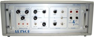
5000 Series High Voltage Linear Differential Amplifier
Very high voltage linear amplifier for driving Pockels cells
 This 5000V series linear amplifier has been designed to drive large aperture electro optic modulators. It consists of two 0.4 – 3.0 kV linear amplifiers that together produce a differential output that can be connected to either side of the modulator. This produces an optical phase change equivalent to the output from a single sided 5000V unit.
The amplifier has a bandwidth of 14KHz and a rise time of less than 5µs.
It incorporates a 1 – 10KHz internal oscillator giving sinusoidal, triangular and square waveforms. For phase modulation applications the positive and negative excursions of the square wave output can be precisely controlled. This differential drive technique increases the lifetime of the modulator by maintaining a zero mean voltage across its terminals.
Specifications
| Output Voltage Range | 400 - 3000V (each side) |
| Full amplitude Frequency Response | 14 KHz |
| Small Signal Frequency Response (10% Full Amplitude) | 100KHz |
| Rise and Fall Time | 5µsec |
| Signal-Noise Ratio | 50dB |
| Input Voltage | -2.5V to + 2.5V |
| Input Impedance | 1000Ω |
| Cabinet Size (mm) | 220 (height), 530 (width), 340 (length) |
| Mains Voltage | 110/200/240ac 50-60Hz |
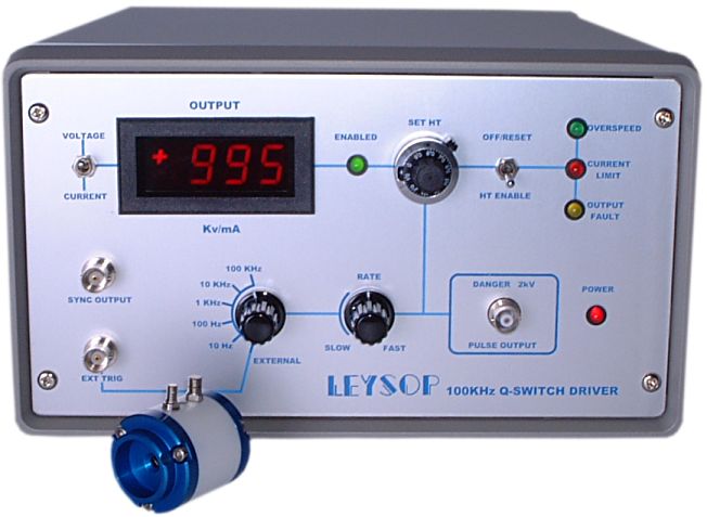
100kHz RTP Pockels Cell Q-switch Driver
High repetition rate Q-switch driver for RTP Pockels cells
 One of the most difficult aspects in dealing with electro-optic devices is the problem of working with high voltages. The majority of electro-optic devices present a capacitive load to the driver which further compounds the problem of finding a suitable driver. However, the relatively low voltage requirements of the transverse field RTP Pockels cell allow Leysop to switch the high voltage at high repetition rates with acceptable power consumption at the driver.
Leysop developed the driver with the application of continuously pumped sources in mind. For this reason no facility for varying the delay from the input trigger pulse and the Q-switch output pulse has been incorporated. Full protection facilities are provided based on internal current limiting to ensure that the demands on the internal HT power supply do not exceed its capability. There is also an internal rate generator for those applications where synchronization to external events is not required and free running use is acceptable.
Safety is paramount and the high voltage output is provided by a safe high voltage (SHV) form of the BNC connector and a matching lead is supplied to connect to the Pockels cell terminals. The HT votage may be set precisely from the front panel to enable the unit to be set for optimum performance at the user’s operating wavelength and to allow for the different voltage requirement of the three aperture options available.
Provisional Specifications:
| Parameter | Value |
|---|---|
| Repetition Rate | 0 to 100kHz in five decade steps by internal or external generator |
| Output Voltage | +200 to +2,000V adjustable with visual display |
| Output Pulse | The standard system generates a positive going step function above zero. The generator can also be supplied giving a negative going step from the set HT level down to zero for quarter wave switching. |
| External Trigger In | +3.0 to 10.0V min. 10ns f.w.h.m. into 50Ω |
| Synchronization Output | TTL approx. 30ns after trigger |
| Overload Protection | (1) Repetition rates above 100kHz (2) HT Current above 25mA (3) Output stage fault overload Protection occurs by automatic removal of the HT supply which can be re-instated by the reset switch |
| Power Input | Universal 90 - 265V a.c. 47 - 440Hz via fused IEC inlet |
| Dimensions | 150(h) x 250(w) x 330(d) (mm) Mass: 6kg |
| 50W co-axial cable length | Rise-Time | Flat Top | Fall Time | Maximum Frequency at 2kV | Maximum Voltage at 100kHz |
| 125mm | 5ns | 175ns | 400ns | 80kHz | 1,700V |
| 250mm | 5ns | 160ns | 500ns | 66kHz | 1,500V |
| 500mm | <7ns | 150ns | 700ns | 50kHz | 1,300V |
| 1,000mm | <8ns | 120ns | 1,000ns | 40kHz | 800V |
