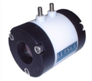
In the field of electro-optics, there are very few occasions when something truly unique is developed. However, one such event was the advent of the new electro-optic material RTP.
- It possesses a large electro-optic effect for light propagating along either the X direction or along the electro-optically more favorable Y direction (electric field in the Z direction).
- It features good optical transparency from around 400nm to over 4μm and very importantly for intra-cavity laser operation, offers a high resistance to optical damage with power handling ~1GW/cm2 for 1ns pulses at 1064nm.
What really sets this material apart from all the others is its essentially total lack of piezo-electric resonances all the way out to 200kHz and probably beyond.

This has been the driver limited range of Leysop’s measurement capability and they report no reason to doubt that it would perform beyond this (driver permitting). This exceptional performance opens up new possibilities for laser manufacturers previously limited to operation to 30kHz using BBO electro-optic Q-switches or forced to use much slower acousto-optic Q-switches (with their longer inherent Q-switched pulse lengths) for operation at higher frequencies. Now, it is possible to break the 30kHz barrier without suffering excessive pulse lengths.
Comparisons with BBO are of course inevitable and we would not wish to give anyone the impression that RTP is the universal panacea for all laser applications. Rather, we believe that with an understanding of its limitations it can offer performance previously unattainable in electro-optic Q-switches.
The main difference between RTP and BBO when used for Q-switching relates to the average power level at which the Q-switch is able to be used practically. That is not to say that it suffers from optical damage, far from it. Its damage resistance is better than most EO materials and is only really bettered by BBO. It is more due to the nature of the implementation of the Q-switch itself.
Unlike BBO in which the optical propagation is along the optical axis of the material, in RTP the light propagation axis is either along the X or Y axes, both of which exhibit birefringence. The usual method of compensating for this is to use a pair of crystals, matched in optical thickness, which are then orientated at 90° to each other such that light which is polarized along the X axis say in the first crystal is then polarized along the Z axis of the second crystal. The “slow” ray in the first crystal then becomes the “fast” ray in the second and the total static birefringence is thus in theory cancelled in the composite crystal pair.
This process is not perfect and even with the best matched crystals a loss of birefringence cancellation can be experienced when high optical powers are passed through the crystals. This is because of the albeit very small, but still significant, optical absorption in the crystals which causes small differences in the local heating of the crystals. This upsets the compensation of the two crystals and unless some dynamically variable biasing arrangement is used a loss of extinction will occur which will degrade the laser performance.
Thus, RTP is most suited to moderate average power laser sources where high repetition rates and short Q-switched pulse lengths are more important than high average powers.
One major advantage over BBO is the much higher electro-optic effect. Typically BBO half wave voltages at 1064nm are ~6.5kV for a 3mm aperture BBO cell compared to just 1,300V for an equivalent sized RTP cell. Given their broadly similar capacitance the power consumption of the RTP cell is just over one tenth that of the BBO cell.
As with all new materials, Leysop encourages users to experiment with RTP to find out its strengths and limitations in real world systems.
Specifications:
| Parameter | Value |
|---|---|
| Transmission at 1064nm | >98.5% |
| Apertures Available | 3, 4 and 6mm |
| Half wave voltages at 1064nm | 1,000V, 1,300V and 2,000V |
| Contrast ratio | >20dB |
| Acceptance Angle | >1° |
| Damage Threshold | >600MW/cm2 at 1064nm (t = 10ns) |
| Physical Dimensions: | 35mm Ø/font>, 45mm long |
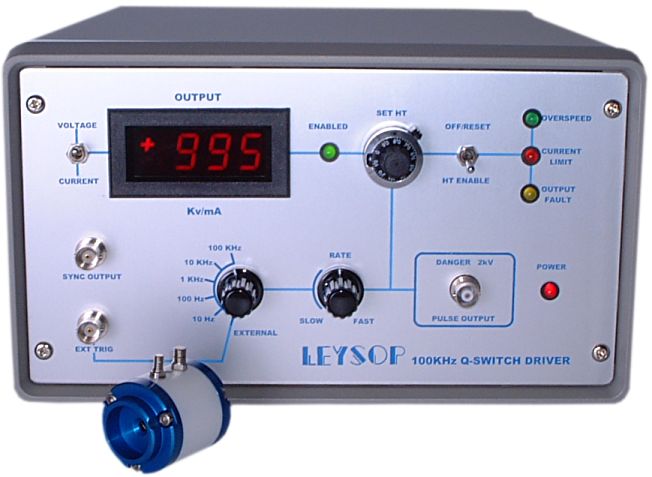
100kHz RTP Pockels Cell Q-switch Driver
One of the most difficult aspects in dealing with electro-optic devices is the problem of working with high voltages. The majority of electro-optic devices present a capacitive load to the driver which further compounds the problem of finding a suitable driver. However, the relatively low voltage requirements of the transverse field RTP Pockels cell allow Leysop to switch the high voltage at high repetition rates with acceptable power consumption at the driver.
Leysop developed the driver with the application of continuously pumped sources in mind. For this reason no facility for varying the delay from the input trigger pulse and the Q-switch output pulse has been incorporated. Full protection facilities are provided based on internal current limiting to ensure that the demands on the internal HT power supply do not exceed its capability. There is also an internal rate generator for those applications where synchronization to external events is not required and free running use is acceptable.
Safety is paramount and the high voltage output is provided by a safe high voltage (SHV) form of the BNC connector and a matching lead is supplied to connect to the Pockels cell terminals. The HT votage may be set precisely from the front panel to enable the unit to be set for optimum performance at the user’s operating wavelength and to allow for the different voltage requirement of the three aperture options available.

Provisional Specifications:
| Parameter | Value |
|---|---|
| Repetition Rate | 0 to 100kHz in five decade steps by internal or external generator |
| Output Voltage | +200 to +2,000V adjustable with visual display |
| Output Pulse | The standard system generates a positive going step function above zero. The generator can also be supplied giving a negative going step from the set HT level down to zero for quarter wave switching. |
| External Trigger In | +3.0 to 10.0V min. 10ns f.w.h.m. into 50Ω |
| Synchronization Output | TTL approx. 30ns after trigger |
| Overload Protection | (1) Repetition rates above 100kHz (2) HT Current above 25mA (3) Output stage fault overload Protection occurs by automatic removal of the HT supply which can be re-instated by the reset switch |
| Power Input | Universal 90 - 265V a.c. 47 - 440Hz via fused IEC inlet |
| Dimensions | 150(h) x 250(w) x 330(d) (mm) Mass: 6kg |
Step Voltage at End of an Open Circuit 50Ω Line
| 50W co-axial cable length | Rise-Time | Flat Top | Fall Time | Maximum Frequency at 2kV | Maximum Voltage at 100kHz |
| 125mm | 5ns | 175ns | 400ns | 80kHz | 1,700V |
| 250mm | 5ns | 160ns | 500ns | 66kHz | 1,500V |
| 500mm | <7ns | 150ns | 700ns | 50kHz | 1,300V |
| 1,000mm | <8ns | 120ns | 1,000ns | 40kHz | 800V |
