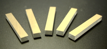
Unlike the EM500 range of Pockels cells, the transverse field Pockels cells can be made in a more flexible range of sizes and in a greater choice of materials. The construction usually consists of either one Z-cut crystal in the case of lithium niobate, or two X or Y cut crystals, orientated for birefringence cancellation in the case of lithium tantalate. Other materials are available to suit special requirements, but none can match these for their established quality and low cost.
For most applications, the designs can be mounted in a simple machined aluminum alloy channel housing of an appropriate size to match the crystal(s). If necessary, this may incorporate special fixing or other dimensional requirements at a moderate cost.

Lithium Niobate (LiNbO3)
Lithium Niobate (LiNbO3) is a very important material for transverse Pockels cell manufacture. It possesses excellent transparency over a wide spectral range of 450nm to just over 4μm. Optical damage can be a problem at short wavelengths because of color center formation. Above 800nm, however, this effectively disappears and the material then has a very good optical damage resistance. This makes it very suitable for Q-switching compact Nd+ lasers such as found in laser rangefinders.
There are two orientations which may be used successfully for lithium niobate electro-optic devices and the choice is usually determined by the application. The first and the simplest involves using a z-cut bar where the optical axis of the material is parallel to the direction of optical propagation so there is no birefringence encountered. This simplifies the design of the optical system as good thermal stability is ensured automatically. The electric field is applied via deposited electrodes on the X faces of the bar. This accesses the r22 electro-optic coefficient which has the value of approximately 6.7 x 10⁻¹²mV-1 for static electric fields and a little over half this for rapidly varying fields.
Why the difference? This is because the static value includes a contribution from the piezo-optic effect where the application of an electric field mechanically strains the crystal and induces an additional optical phase change. For changes of electric field which occur sufficiently quickly, the molecular displacement required to induce the additional strain component cannot follow the electric field and the material operates in the so called “constant Strain” or “clamped” mode and sensitivities are much lower. It is therefore important to be sure of whether stated half wave voltages are defined at dc or under ac drive.
Although this orientation provides a simple mode of operation, the r22 electro-optic coefficient is not especially high and the difference between the ac and dc values may be significant for some applications (especially where modulation at low to moderate frequencies is required). In this case, an alternative orientation using optical propagation down the X axis with the electric field applied across the Z axis is available. This utilizes the r13 electro-optic coefficient which has the value of approximately 8.6 x 10⁻¹²mV-1. As this orientation is not piezo electrically active, there is no significant difference between the clamped and unclamped electro-optic coefficient and ac and dc fields produce the same modulation. This mode of operation however is not well suited to Q-switching because two crystals must be employed, orientated for static birefringence cancellation. The additional surfaces cause extra loss and increases potential problems with multiple reflections etc. This type of device is not therefore as popular as the more usual Z-cut modulator.
Some examples of the typical static field half wave voltages (Vp) of a transverse lithium niobate cell using the z-cut geometry and suggested sizes are given in the following table. Remember to approximately double these for fast switching applications (such as Q-switching).
Dimensions (mm)
9 x 9 x 25
3 x 3 x 12
2.5 x 2.5 x 36
Vp (1064)
3.05kV
2.13 kV
0.65 kV
Vp (633 nm)
1.45 kV
1.03 kV
0.29 kV
Lithium Tantalate (LiTaO3)
Lithium tantalate does not possess any useful r22 electro-optic coefficient and so is not used in an optic axis propagation mode. Instead, it is orientated such that light propagates down the Y axis and the electric field is across the Z-direction. Thus a combination of the r13 and r33 electro-optic coefficients are active. As this is a birefringent axis, a composite pair of crystals is again used for birefringence cancellation and if well matched crystals are used the temperature stability is reasonably good (due in part to the relatively small value of birefringence).
At first glance, there would seem to be little advantage to using lithium tantalate over lithium niobate in the z-cut mode. However, lithium tantalate has little piezo-electric activity and so its dc and ac response are very similar. One consequence of the piezo-electric activity in lithium niobate is that at certain frequencies it may be possible to set up acoustic resonances in the device when driven in a repetitively pulsed mode for example. This causes distortions in the modulation such as ringing of the optical transmission, and worse still, under hard excitation can lead to premature destruction of the crystal. This severely limits the use of lithium niobate for some applications, but no such limitations occur in lithium tantalate until very high frequencies are encountered. Also, the optical transmission range of lithum tantalate is similar to lithium niobate, but it does not suffer the short wavelength optical damage effects described earlier. This makes it particularly suited to moderately high power visible laser applications with for example argon ion and frequency doubled Nd+:YAG lasers.
Some example sizes and performances are given in the following table (remember that these values apply both to dc and ac driven applications, but dimensions refer to each crystal of the composite pair):
Dimensions (mm)
3 x 3 x 12
2.5 x 2.5 x 24
Vp (1064 nm)
630 V
263 V
Vp (633 nm)
350 V
146 V
Vp (458 nm)
217 V
90 V
